
Rhino NURBS Solid Modeling Tutorial

The final product should look something like this
This tutorial is based on toxiclab’s webcam tutorial. I tried to be a little more explicit as this is intended for beginners.
Colors in the screenshots are only intended to distinguish between steps. Enjoy!
| Webcam file with all steps (.3dm, 16mb) | |
| Step 1.a Start a new file (small obj/inches) |  |
| Step 1.b In the Top viewport, draw 2 concentric circles, centered on 0, 1″ and 2″ diameters respectively. |  |
| Step 2 Copy and paste the smaller circle in place. |  |
| Step 3 Turn on Osnap and activate Cen only. Activate Move command, snap to Cen of copied small circle, then type <45 to add an angle constraint. |  |
| Step 4 Move small circle outward so that it intersects with the outer circle. |  |
| Step 5 Activate the ArrayPolar command. Select the small circle to array. Set 0 as the center of the array. Set the number of items to 4. Set the angle to 360. Hit Enter. |  |
| Step 6.a Select the four small circles. Activate the Split command, and split the large circle. |  |
| Step 6.b Select the large circle, then activate the Split command and split the four smaller circles. |  |
| Step 7 Select the four larger segments of the outer circle, and the four smaller segments of the outer circles–they’ll form a rounded cross-shape. Join these curves with the Join command. |  |
| Step 8 Turn on grid snapping. Select the innermost circle, and move it up one inch in the RIght or Front viewport by clicking and dragging. | 
 |
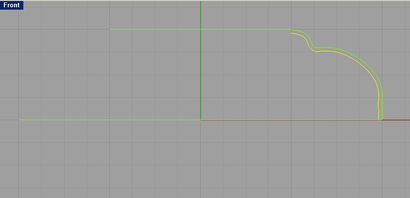
| Step 9 In the Front viewport, turn on grid Snap. Activate the Interpolate Points curve tool. To draw the first point, snap to the grid intersection on the x axis that is two inches to the right of zero. Then turn Snap off. Draw a line that is the approximate shape shown – it does not have to match perfectly. To draw the last point, turn Snap back on, and snap to the grid intersection that is 1″ above the x-axis and 1″ to the right of the z-axis. |  |
| Step 10 Select the curve you just drew, then activate the Offset command. Set the Distance to 0.04″, and offset below the original curve. | 
 |
| Step 11 While still in the front view, disable Osnap, and turn grid Snap on. |  |
| Step 12 Select the curves from step 10, and activate the Revolve command. Set the start of the revolve axis by entering 0, then set the end of the revolve axis by snapping to any grid intersection that lies directly above zero. Select the Fullcircle option. |  |
| Step 13 Select the outer cross-shaped curve and activate the extrude curve command. Extrude the curve straight up so that the resulting surface is higher than the revolved surface from step 12. |  |
| Step 14 Select the extruded surface and the outer revolved surface, then activate the Intersect command. This will create a curve on the revolved surface that traces all intersection points with the extruded surface. Now select and delete the extruded surface from Step 13. |  |
| Step 15.a Select the intersection curve from step 14, then activate the Explode command. Select just one of the circular arcs (it doesn’t matter which). |  |
| Step 15.b Enable Osnap with only the End option checked. Enable Ortho. Disable grid Snap. Use the Line command to draw straight lines pointing downward from both ends of the arc. Do this by Osnapping to the end for the first point, then use a length constraint of 1″ to drop the end of the line straight down 1″. |  |
| Step 15.c Do this for both ends of the current arc, as well as the opposite arc. |  |
| Step 16 Select each pair of vertical lines that are opposite one another, and activate the Loft command to create a surface between them. Use the default Loft options. |  |
| Step 17.a Activate the EdgeSrf command. Select the two opposite arcs from step 15, as well as the top surface edges from the lofts in step 16 to define four sides of a surface. |  |
| Step 17.b Now select the two lofts and the 4-edge surface and Join them. |  |
| Step 18 Select the joined surface from step 17. In the top veiwport, activate the Scale1D command. Set the origin to 0. Add an angle constraint of 45 degrees to the first reference point by typing “<45,” then click in the lower right quardant of the viewport, outside the revolved surface. Drag the second reference point outward until the ends of the joined surface extend outside the revolved surface. |  |
| Step 19 In the Top viewport, select the scaled surface from step 18. Activate the Rotate command. Type C or click the Copy option to rotate a copy of the selected surface. Set the center of rotation to 0. Set the angle to 90. |  |
| Step 20 Select both rotated surfaces from step 19. Activate the Trim command. In the Perspective viewport, click on the inner and outer sections of the revolved surface that are underneath the arcs of the surfaces from step 19. Delete the surfaces that were used as cutting objects. | 
 |
| Step 21.a In the top viewport, activate the Plane command. Draw a plane that is larger that the revolved surface. |  |
| Step 21.b In the Top or Front viewport, ctivate grid Snap, and drag the plane up 1/2″ by clicking and dragging. |  |
| Step 22 Select the plane from step 21, then activate the Trim command. In the Right or Front viewport, trim off the parts of the revolved surface that are below the plane. Delete the plane after trimming. | 
 |
| Step 23.a In the top viewport, activate the Plane command again. Draw a plane that is larger than the revolved surface. |  |
| Step 23.b Select the revolved surfaces, then activate the DupBorder command to extract curves from the surface’s edge. With the curves still selected, activate the Project command from the Top viewport, and select the Plane from step 22 to project onto. Delete the Plane from this step. | 
 |
| Step 24.a Loft a vertical surface between each set of curves–select the inner top and inner bottom, then activate the Loft command. Set the style to Normal and Do Not Simplify Cross-section curves. |  |
| Step 24.b Do the same for the outer top and outer bottom curves. |  |
| Step 25 Select the two bottom curves, then activate the PlanarSrf command to create a bottom surface. |  |
| Step 26.a Turn on grid Snap and Osnap, with only the Knot option checked. Activate the Sphere command. Type ‘3’ or click on 3Point to define a sphere using three points. For the first point, snap to one of the four knots on the inner revolved surface that is around the open circle on the top. |  |
| Step 26.b For the second point, snap to the knot opposite the first one you selected. |  |
| Step 26.c For the third pick, enter the point with world coordinates (0,0,3). ‘w0,0,3’ in the command line. |  |
| Step 27 Use the inner/lower revolved surface to trim off the top portion of the sphere from step 26: select the inner revolved surface, then activate the Trim command. Select any part of the sphere that lies above the revolved surface as the surface to trim. |  |
| Step 28 Repeat step 26, but this time use the knots on the upper revolved surface. Use the same coordinates for the third point. |  |
| Step 29 Repeat step 27, but this time use the upper revolved surface to trim the sphere created in step 28. |  |
| Step 30 Select all the surfaces, then join them into a solid by activating the Join command. Check with the What command to make sure you have a valid polysurface that is closed and solid. |  |
| Step 31 In the Top viewport, turn on grid Snap, and deactivate Osnap. Activate the Rectangle command. Select the Center option by clicking or typing ‘C’, then select Rounded by clicking or typing R. The center of the rectangle should be 0. The corner of the rectangle should be placed at the grid intersection three units to the left and one unit up from the center. For the radius point, snap to the grid intersection that is three units to the left of the origin. |  |
| Step 32 Select the rounded rectangle from step 31. Activate the ExtrudeCrv command. Set the Cap option to Yes. Extrude the curve so that it intersects through the sphere bottoms above it. |  |
| Step 33 Select both the joined surface and the extruded rectangle. Activate the Boolean2Objects command. Click through the left mouse button to see the different iterations. Click until the rounded rectangle has carved an empty space from the middle of the sphere-bottoms. Hit Enter. |  |
| Step 34 Turn off grid Snap and Ortho. Turn on Planar. Turn on Osnap, but make sure all the boxes are unchecked. Enable the Strack option only. Draw a shape similar to an invered numeral 1. In the Right viewport, Activate the Polyline command. Start the first point slightly to the right of the Z-axis and a bit above the rim of the joined surface. Hold down shift to draw the second part directly below the first. Keep using shift to draw horizontal and vertical lines. When you get to the second-to-last point, Snap briefly to the first point. This will create a SmartTrack line to indicate when the second-to-last point is even with the first. Use the Strack line while holding shift to set the point, then Snap to the first point to close the shape. |  |
| Step 35 Activate grid Snapping. Select the shape created in step 34, then activate the Revolve command. Set the start and end points by Snapping to two grid inersections that both lie on the Z-axis. Select the Fullcircle option. |  |
| Step 36 Make sure grid Snap is still activated. In the Top viewport, activate the Sphere command, and start the center of a sphere 1″ above the X-axis and 1″ to the right of the Y-axis. Set the radius of the sphere to 0.025″. |  |
| Step 37.a Turn on Osnap and select the Cen and Quad options. Activate the OrientOnSrf command. Select the sphere from step 36 as the object. Set Reference point 1 by snapping to the Cen of the sphere. |  |
| Step 37.b Set Reference point 2 by snapping to one of the four isocurve intersections adjacent to the sphere’s center. |  |
| Step 37.c Select the top of the joined surface as the Surface to orient on. A dialog box will appear. Leave the settings at default and hit OK. |  |
| Step 37.d Set the Point on surface to orient to by snapping OnSrf to a point on the outer surface of the joined surface. Be careful not to select the lower surface! | 
 |
| Step 38 In the Top viewport, select the sphere from step 37. Activate the ArrayPolar function. Set the center of the array to 0. Set the number of items to somewhere around 30-75. Set the angle to fill to 360. |  |
| Step 39.a Activate the BooleanDifference command. Set the joined surface as the first set. |  |
| Step 39.b Set all the spheres from step 38 as the second set by click-dragging in any view to select them all. | 
 |
| Step 40 Turn on grid Snap and Osnap with Quad selected. Activate the Sphere command and draw a sphere from three points like in step 26. The first two points are the opposing Quads on the upper revolved surface. The third point is the point with world coordinates (0,0,3) [‘w0,0,3’] | 
 |
| Step 41 Select the solid base and revolved piece from step 35 and activate the Hide command. |  |
| Step 42 Turn off Osnap and make sure grid Snap is still on. From the Top viewport, activate the Box command. Click Center or type ‘C’ to draw a box from the centerpoint. Snap to the grid origin to define the first point. For the length, type ‘4’. For the width, type ‘0.1’. For the Height, type ‘4’. |  |
| Step 43 From the Top viewport, select the box from step 42. Copy and paste it in it’s location. Click and drag the pasted box one unit up. Copy and paste the original box again, and this time drag it one unit down. |  |
| Step 44 Turn on Osnap with only the Cen option active. Make sure grid Snap is on. In the Right viewport, select the three boxes from step 43. Activate the Rotate command, and click on Copy or type C to duplicate the boxes. Snap to the center of the sphere from step 40 to set the cener of rotation. Set the angle of rotation to 90. |  |
| Step 45 Select the sphere from step 40, then activate the BooleanDifference command. Select all of the boxes as the second set of polysurfaces. |  |
| Step 46 Disable Osnap, and make sure grid Snap is on. In the Right viewport, activate the Sphere command. Snap to the grid intersection at the center of the cut-up sphere to set the center-point. Now turn grid Snap off. To set the radius, hold down shift and move the cursor straight up from the center-point. Set the radius so that the sphere’s surface is about half a grid unit from the cut-up shpere’s surface. | 
 |
| Step 47 Select the sphere from step 46 and all the sphere chunks from step 45. Activate the BooleanUnion command. |  |
| Step 48 Disable Osnap, and make sure grid Snap is on. In the Right viewport, activate the Circle command. Set the center of the circle by snapping to grid inersection at the cener of the sphere from step 47. Set the Radius to .5″. In the Top viewport, click and drag the circle to move it one inch to the left. |  |
| Step 49 With the circle from step 48 still selected, activate the ExtrudeCrv command. Click on Cap or type ‘C’ to create a capped solid extrusion. Extrude the curve to the left so that it extends through the surface of the sphere from step 47. |  |
| Step 50 Select the sphere from step 47. Activate the BooleanDifference command. Select the extruded cylinder from step 49 as the second set of polysurfaces. | 
 |
| Step 51 Activate the FilletEdge command. Click CurrentRadius or type ‘C’ and set the radius to 0.05″. Select the top edges of the crown shape formed in step 50 as the edges to fillet. | 
 |
| Step 52 Turn off grid Snap. Turn Planar on. Turn on Osnap, and select only the Quad option. In the Perspective viewport, rotate your model so that the camera is facing the flat circular surface formed in step 50. Activate the InterpCrv command. Set the first point by snapping to the quad on the left side of the flat surface. Disable Osnap after setting the first point. Then from the Top viewport, draw a curve as shown. |  |
| Step 53 Still working in the Top view, turn Osnap on and select only the End option. Activate the Line command and draw a line as shown, snapping the first point to the end of the curve drawn in step 52. Set the second point so that the line intersects the flat face of the spherical body. |  |
| Step 54 Still working in the Top view, turn Osnap on and select only the End option. Activate the Polyline command. Snap to the end of the line created in step 54 to set the first point. Turn off Osnap to set the rest of the points, and draw a zig-zag line as shown. To set the last point of the line, turn on grid Snapping and snap to the grid origin. |  |
| Step 55 Turn on grid Snap. Select the three curves created in steps 54, 53, and 52. Join them, then Activate the Revolve command. In the Front viewport, set the start and end of the revolve axis by snapping to two adjacent grid intersections that are in line with the selected curves. Set the start angle to 0, and the revolution angle to 360. |  |
| Step 56 Select the ring-shaped surface formed by the revolution of the curve from step 52. Activate the Trim command, and Trim the flat part of the main spherical surface. |  |
| Step 57 Select everything in the scene by hitting Ctrl+A. Activate the Join command to join all the surfaces into a solid (if you’ve done it right :) |  |
| Step 58 Activate the Show command to unhide the base and the smaller piece from step 41. Select the base, then activate the Hide command again. Now select the main solid surface from step 57 and the remaining revolved surface. Use the BooleanDifference command with DeleteInput set to No to cut into the spherical body. Activate the Show command to show the base. | 
 |
Many thanks for excellent step by step tutorial, a great help to newcomer to Rhino after years with other CAD programs.